Buggy Model
"Bishop" - Realistic Buggy Model
2018

Bishop is modeled after the newest Fringe buggy. The signature fairings around the wheels make for a sleek design. Combining several fabrication techniques I used throughout 2018, I designed and created this model buggy to be as realistic as possible for its scale.
As Bishop has several realistic buggy features, it was tricky to scale them down and have realistic build processes. Mimicking actual buggy builds was a major influence to my fabrication processes.
Product features
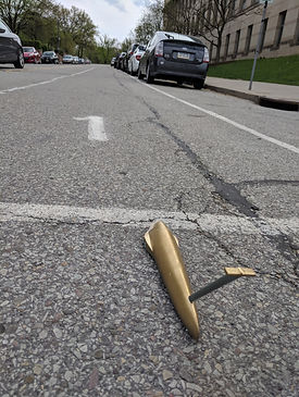
• Metallic gold spray-painted finish
• Pushbar insert press-fit into shell and reinforced with epoxy
• 3D-printed SLA resin two-part shell designed from actual buggy model
• Wheels made from laser-cut acrylic and fitted to the fairings and axles
• Windshield laser-cut from plastic sheet then bent with heat to fit shell
• Aluminum axles held in place with epoxy, like a real buggy
This model was meant to be more accurate and intricate than the previous models I cast out of resin. A real-size buggy is driven by students around 5 feet tall. They are pushed up the on-campus course and they drive on the free-rolling portion of the course. Buggy races culminate in April at Spring Carnival, where each team gives it their all to push and drive their buggies around the course as fast as they can.
Process
Ideation
I have wanted to make a buggy model since I made my first buggy with my team. The initial idea came from the desire to test out paint jobs on some realistic model. With the resources and skills needed to make a truly realistic model, I sought inspiration from our actual buggy design in addition to rapid prototyping processes. My inspiration for the product and for design, respectively, are shown below in mood boards.


Design
Design Process:
-
Edited the Solidworks model of team's buggy for this year, "Bumper"
-
Scaled the model down from 6 feet long to 12 inches long
-
Removed unnecessary features such as steering mechanisms
-
Constructed models for wheels that would fit the purchased axle size while maintaining appropriate height off the ground
-
Solidified pushbar to allow rigidity
-
Shelled out body to decrease weight and print cost
-
Cut out hatch opening to allow for windshield transparency effect
-
Combined features to create one solid part that could be used as an STL file for printing


Printed Parts
The 3D-printed parts were printed on a Form 2 SLA printer. I intended to print them on the Ultimaker 3 Extended printers, but my first attempt on those failed to complete printing. If not for the build plate size constraint, I would have preferred to print the whole buggy at once, but to account for this I split the buggy along a plane around the center of mass and made two halves. The design for the front and rear halves included three inserts to help them interlock better when attaching.
After printing, I had to post-process the materials by cleaning them in isopropyl and then curing them in an oven at 60°C for 30 minutes. The two halves of the buggy came out well, but the first pushbar iteration came out extremely weak, and ripped almost instantly. To account for this, I printed a new pushbar that was solid all the way through. I also had to print a second rear half because I dropped the first iteration and it shattered. The second rear half came out solid and remained intact.


Axles & Wheels
The front axle came from a standard pine car derby kit that I purchased. The rear axle was simply a nail that came with the kit which I cut down with pliers then sanded. The housing for the axles was intended to stay inside the buggy, but when I drilled them out, both when testing with a drill press and a hand drill, the resin shell was too weak and shattered. I utilized my dropped rear shell for testing hole sizes and resin integrity. The front left axle housing did manage to stay intact, though.
I laser cut the wheels from a sheet of 1/8" acrylic. I experimented with the outer and inner diameters to determine what the ideal fit was given the laser cutter's kerf. I also experimented with double-width wheels in the front to account for the empty space where a real buggy's spindle and brakes would go. The double wheels worked better, so I made a set of them simply using superglue while keeping the center holes aligned on a nail. The wheels rotated around static axles. The front wheels were kept in place by the end caps from the derby kit and the rear wheel was kept in place by the rear fairing.


Epoxy
In traditional buggy fashion, I used a lot of epoxy for my final steps. I used West Systems Five-Minute Adhesive, which requires a simple 1:1 ratio of hardener to resin. I mixed the epoxy with what I had a around me (plastic knife, chopsticks) and then applied it to each area where I needed it. I used epoxy in the internal cutout of the buggy where the pushbar was inserted, connecting the two halves of the buggy shell, and to fix the axles in place. For each of these, I slightly sanded down the area of application to increase epoxy bonding surface area. When connecting the two halves of the buggy, it was difficult to maintain a perfect alignment. Due to the three inserts, I was able to keep the alignment close enough that, when sanded, the buggy was smooth at the joint line.


Windshield
To cut out the windshield shape, I used the shape we used for our own buggy and scaled it down. This was acquired by taking the 3D model and then flattening it out in Solidworks. Usually, we print out the sheet and manually cut out the shape. Instead of doing this, I realized that I could laser cut the plasti with the DWG file I already had. I then had plastic cutouts that I bent over the model to get it into shape. Using what I learned from my acrylic cupholder project, I heated up the plastic to bend it cleanly. The first iteration came out rather messy, likely due to my repeated changes in hand position to bend it into place. On the second iteration, I asked a peer to hold the heat gun stationary while I bent the plastic into place, which yielded a much cleaner result. I held the windshield in place with superglue.


Paint
I did all my spray painting in an open area, with atmospheric ventilation,moderate wind, and about 60% humidity. I experimented with paint results on the spare rear half that I had left over. I tested one side with just gold spray paint, and the other side with primer first. The primer-first side had much better results so I decided to use primer on my final paint job. I used two coats of primer, around 20 minutes apart. Then I applied one coat of gold, followed by another after about 1 hour. To get the pushbar to be a different color, I taped it up before applying the gold paint.
